This optional Remote Control/Monitor GUI Software (Lightwinder Commander) runs on a Windows® PC connected to the HOST connector (USB) on any LWB unit in the system and provides remote controlling and monitoring of the whole LWB system. Although the LWB system is designed to run without any PC control, GUI control/monitoring of the entire system has been desired. With Lightwinder Commander, operators can:
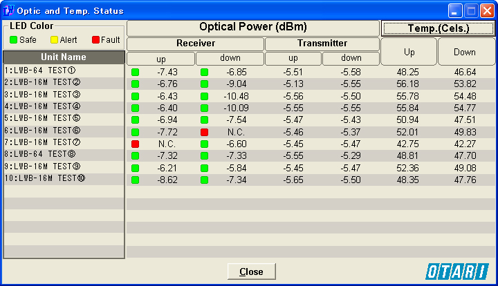
Watch the status of the entire system including the optical power level and temperature of the optical transmitters
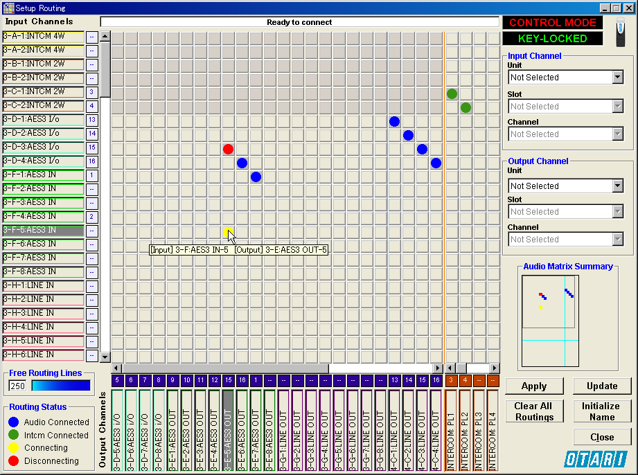
Set, change and monitor the routing of the audio and intercom channels in an intuitive matrix
Control all of the channel parameters remotely
Store multiple routing/channel parameter settings as setup files and recall any of them to apply (since the setup file is in CSV format, you can quickly edit it with spreadsheet software or a text editor).
Supported languages: English and Japanese
PC Requirements
Windows® 2000/XP/Vista
Two unused USB ports
XGA (1024x768) video monitor
Windows is a registered trademark of Microsoft Corporation. Specifications and GUI design are subject to change without notice.
Main Screens
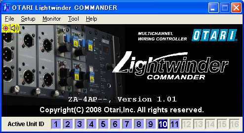
Main Window:File operation commands and various control windows are accessed from this screen. (Click image to enlarge)
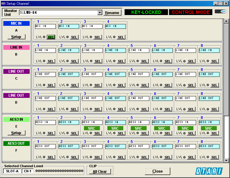
Setup Channel Window:This window is for monitoring the status of the modules and channels of the selected LWB unit. Unit and channel names can be changed in this window. A 3-color LEVEL indicator is provided for each channel and the signal level of the selected channel is indicated by the bargraph meter at the bottom of the window. Clicking on the Setup button on the module column opens the detailed setup window for each module. (Click image to enlarge)
Mic Amp Setup window:This window for adjusting microphone channel amplifier parameters is displayed by clicking on the Setup button on the MIC IN module in the Channel Setting window. Each channel can be renamed in the name field. The +48-volt phantom power is turned on/off by clicking on the +48V button. Similarly the pad and limiter can be activated by clicking the corresponding buttons. Microphone amplifier gain is adjusted with the fader and trim buttons.Note that the pad attenuation value can be added to the displayed gain value. The UNITY button is provided to set the channel to unity gain. The channel selection buttons and LEVEL indicators are duplicated here in this window as on the MIC IN module front panel.
Clip (Gain Adjust) Window:When clipping occurs in an audio channel, this window opens for warning and for readjustment of the gain.
Setup Routing Window:A matrix type routing screen to connect audio/intercom signal channels. (Click image to enlarge)
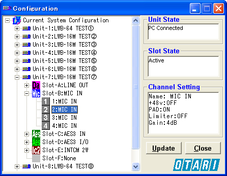
Configuration Window:A tree type list to show the configuration of all of the units connected. (Click image to enlarge)
Optic & Temp. Status Window:This window shows the operation status (optical power level and transceiver temperature in °C or °F) of the optical transmitters for upstream and downstream sides. (Click image to enlarge)
 home
home